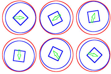
English: Mechanical precession is the process of a round part (in blue) in a round hole (in red) rotating in the direction opposite to the applied radial force (in green).
I made this with the following Octave code:
%%%% This octave script draws a set of figures that
%%%% demonstrate Mechanical Precession.
%%%% It is very similar to the animation of a Hypotrochoid.
%%%% http://commons.wikimedia.org/wiki/File:HypotrochoidOutThreeFifths.gif
%%%% The figures are saved as a series of gifs, and
%%%% compiled into a single animated gif named
%%%% mechanical_precession_x_sides.gif

% Number of turn made by the inner circle before looping
numberOfTurns=3;
% number of frames produced is numberOfTurns * timeResolution
% higher is a smoother but slower animation
timeResolution=20;
% Radius of outside circle (all distance measurements are unitless)
radiusOutside=1;
% 6 for hexagon, 4 for square etc.
polygonSides = 4;
% Radius of inside circle is calculated this way so that in numberOfTurns
% the innerCircle will rotate enough to arrive at a symmetric position on the polygon
radiusInside=(numberOfTurns * polygonSides)/(numberOfTurns * polygonSides + 1) * radiusOutside;
% so we have nice integers in the file names
count=0;

polygonOriginalPoints=radiusInside*.5*exp(i * 2* pi * (0:polygonSides) / polygonSides);
polygonOriginalPoints= [real(polygonOriginalPoints); imag(polygonOriginalPoints)]';

% Arrow to indicate the direction of the radial force
arroworiginalpoints=[1, 0; 0, 1; 0, .5; -1, .5; -1, -.5; 0, -.5; 0, -1; 1, 0] * [.3, 0; 0, .1];
close all;
for theta1=linspace(0, (numberOfTurns - 1/timeResolution) * 2*pi, timeResolution * numberOfTurns)
hold off
% draw outside circle
x1=0;
y1=0;
thetadummy = linspace(0, 2*pi, 100);
circ1x = 1.03 * radiusOutside * cos(thetadummy) + x1;
circ1y = 1.03 * radiusOutside * sin(thetadummy) + y1;
plot(circ1x, circ1y, 'r', "linewidth", 15)
hold on

% draw inside circle
% centre of inside circle rotates by an angle theta1
x2=(radiusOutside - radiusInside) * cos(theta1);
y2=(radiusOutside - radiusInside) * sin(theta1);
thetadummy = linspace(0, 2*pi, 100);
circ2x = radiusInside * cos(thetadummy) + x2;
circ2y = radiusInside * sin(thetadummy) + y2;
plot(circ2x, circ2y, 'b', "linewidth", 15)

% draw polygon
% amount that polygon rotates is theta1 counterclockwise and theta2 clockwise
% the two angles are equated by sustending the same arclength
% radiusInside * theta2 = radiusOutside * theta1
% theta2 = radiusOutside * theta1 / radiusInside
% rotPolygon = theta2 - theta1 = radiusOutside * theta1 / radiusInside - theta1 (clockwise)
% Polygon is centred at (x2,y2)
rotPolygon = (radiusOutside / radiusInside - 1) * theta1;
% multiply by a rotation matrix, add a translation matrix
  pPolygon=polygonOriginalPoints * [cos(rotPolygon), -sin(rotPolygon); sin(rotPolygon), cos(rotPolygon)] + [x2 * ones(length(polygonOriginalPoints),1), y2 * ones(length(polygonOriginalPoints),1)];
plot(pPolygon(:,1), pPolygon(:,2), "linewidth", 20);

% draw arrow
% rotated by theta1
parrow = arroworiginalpoints * [cos(theta1), sin(theta1); -sin(theta1) cos(theta1)];
plot(parrow(:,1), parrow(:,2), 'g', "linewidth", 12);

axis square
axis image
axis "off"
fn=strcat("fig",sprintf('%03d',count),".gif");
count++;
% The size value is a big large but images will be resized later for anti-aliasing
print(fn, "-dgif", "-S2500,2500");

pause(.1);
end

convert_command = strcat("convert -loop 0 -shave '90x90' -resize '440x440' fig*.gif mechanical_precession_", num2str(polygonSides),"_sides.gif");

system(convert_command);


